
When a furnace cannot reach target temperature, production efficiency, product quality, and
energy costs can all suffer. In alloy processing and high-temperature applications, this issue often
points to heating element wear, power supply instability, insulation loss, or control system faults.
Understanding the root causes early helps reduce downtime and protect critical components
such as SiC and MoSi2 heating elements.
For alloy producers, heat treatment workshops, powder metallurgy lines, and high-temperature
material plants, this is rarely a minor deviation. A shortfall of 20°C to 80°C can change sintering
results, oxidation behavior, grain structure, and dimensional consistency. If the furnace cannot
reach target temperature for several cycles, the risk extends from scrap and rework to
accelerated wear of refractory parts, protective tubes, and heating elements.
In many cases, the problem is not caused by a single failure. It is often the result of 3 to 5 factors
acting together, such as aged SiC rods, poor terminal contact, unstable voltage, damaged
insulation, incorrect controller settings, or excessive furnace loading. A structured
troubleshooting process helps maintenance teams identify the true bottleneck without replacing
components blindly.
This guide focuses on alloy-industry furnaces using silicon carbide heating elements,
molybdenum disilicide heating elements, silicon carbide protective pipes, and graphite
components. It also reflects practical concerns relevant to procurement and maintenance teams
that need durable high-temperature parts, shorter shutdown time, and more stable thermal performance.
Why a Furnace Fails to Reach Setpoint in Alloy Processing
When a furnace cannot reach target temperature, the root cause usually falls into one of 4
categories: heating capacity loss, power delivery issues, thermal loss, or control error. In alloy
applications, these categories interact more strongly because operating temperatures may range
from 1000°C to 1700°C, and thermal uniformity is often as important as peak temperature.
- 1. Heating Element Degradation
SiC and MoSi2 heating elements gradually change in resistance during service. SiC elements
typically experience resistance increase as they age, especially under oxidizing atmospheres and
frequent thermal cycling. Once resistance rises beyond the power system’s compensation range,
the furnace may heat more slowly or stop 30°C to 100°C below the required setpoint.
MoSi2 elements can also degrade if they are contaminated, mechanically stressed, or operated
with poor support alignment. In alloy furnaces, localized overheating near terminals or
unsupported hot zones may create partial failure before complete breakage appears. This is why
visual inspection alone is not enough
- 2. Power Supply and Electrical Connection Problems
A voltage drop of 5% to 10% can noticeably reduce furnace output, particularly in systems
already operating near their design limit. Loose clamps, oxidized contact points, cable aging,
transformer mismatch, or phase imbalance can all reduce effective power transfer. In a 3-phase
furnace, one weak phase may cause uneven heating and a delayed approach to target temperature.
Electrical losses are common after maintenance work, element replacement, or long production
campaigns. Terminals that look acceptable may still produce excessive contact resistance. This
becomes more serious in high-current systems where even a small resistance increase generates
heat at the connection rather than in the furnace chamber.
- 3. Insulation and Structural Heat Loss
If the furnace shell becomes hotter than normal, thermal insulation may be failing. Cracked
refractory, compressed fiber modules, worn door seals, damaged peep holes, and gaps around
thermocouple entry points can increase heat loss by 10% to 25% in severe cases. The heating
system may still function, but more input power is consumed to maintain the same chamber temperature.
In alloy applications with frequent charging and discharging, door-related leakage is a common
issue. Furnaces operating in continuous shifts may gradually lose insulation integrity without a
sudden visible failure, which makes trend monitoring important.
- 4. Control System or Sensor Inaccuracy
Sometimes the furnace appears unable to reach target temperature, but the real problem is
inaccurate measurement. A drifting thermocouple, poor compensation wiring, wrong controller
parameters, or incorrect sensor placement can create a 15°C to 60°C reading error. Operators
may think heating output is low when the actual chamber temperature is already close to the process target.
For alloy heat treatment, a misread temperature can be just as harmful as a real heating deficit
The result may be under-sintering, poor diffusion, oxide scale inconsistency, or hardness variation across the batch.
The table below helps maintenance teams distinguish major causes when a furnace cannot reach
target temperature in different operating conditions.
| Observed Symptom | Likely Cause | Recommended Check |
| Slow heating across all zones | Overall element aging or low input voltage | Measure element resistance, verify transformer output and line voltage |
| One area colder than others | Phase loss, partial element failure, poor connectio | Check current balance, inspect terminals, compare zone resistance |
| Furnace shell hotter than usual | Insulation loss or door seal leakage | Inspect refractory lining, seals, observation ports, hot spots |
| Displayed temperature unstable | Thermocouple drift or controller issue | Calibrate sensor, verify PID settings, review wiring integrity |
The key point is that similar symptoms may come from different causes. Replacing heating elements too early may solve nothing if the true issue is a 3-phase imbalance or severe insulation leakage. A step-by-step diagnosis is usually faster and less costly than trial-and-error maintenance.
A Practical Troubleshooting Process for High-Temperature Alloy Furnaces
A reliable process should move from the simplest checks to the most component-specific analysis.
For most alloy plants, the best sequence includes 5 steps and can often identify the main fault
within 1 to 3 maintenance hours, provided basic measurement tools are available.
- Step 1: Confirm the Temperature Gap and Process Conditions
Record the setpoint, actual reading, heating time, load weight, and atmosphere condition for at least 3 recent cycles. A furnace that stops 40°C short under full load but reaches setpoint when empty may have a capacity or loading problem rather than a total electrical failure. Compare current performance with the original heating curve if available
Also verify whether the issue appears during ramp-up, soaking, or both. A slow ramp may indicate low power output, while temperature loss during soaking may point more directly to insulation leakage or unstable control.
- Step 2: Inspect Heating Elements and Resistance Balance
For SiC elements, compare measured resistance values across similar positions. Significant deviation between parallel elements can indicate aging imbalance. In many furnaces, resistance variation above 10% to 15% between matched elements is enough to affect uniform heating. Replace elements in logical groups when needed instead of mixing heavily aged rods with new ones.
For MoSi2 elements, inspect hot zone shape, terminal condition, support alignment, and signs of contamination. Cracks, necking, glaze changes, or distorted geometry can all reduce heating efficiency before total failure occurs. If the furnace operates above 1600°C, even minor installation stress becomes more critical.
Key inspection points
Measure cold resistance after safe shutdown and isolation.
Check whether all element terminals are tight and clean.
Look for localized oxidation, cracking, or abnormal color change.
Verify spacing between elements and nearby refractory surfaces.
Review element service life under actual operating temperature.
- Step 3: Check Voltage, Current, and Connection Quality
Use a meter to compare phase voltage and current under load, not only at idle condition. A no-load reading may appear normal while the circuit drops under heating demand. Current imbalance greater than 8% to 10% should be investigated immediately, especially in furnaces with multiple zones or long busbar paths.
Pay attention to terminal hardware, braid connections, transformer taps, thyristor output, and cable insulation. In some alloy plants, oxidation around terminals grows slowly due to repeated exposure to hot dust and atmosphere leakage. The result is reduced power transfer and higher local heating at the connection point.
- Step 4: Evaluate Heat Loss and Furnace Sealing
Inspect door seals, roof joints, wall lining, thermocouple ports, and any repaired refractory sections. Uneven shell temperature is a useful indicator. If one side is consistently 15°C to 30°C hotter than the opposite side on the outer shell, internal heat loss may be concentrated in that section.
In alloy sintering and melting support operations, operators sometimes focus only on the heating element while overlooking load fixtures, saggers, and graphite supports. Distorted or overly dense loading furniture can block heat flow and increase thermal mass, extending the heating time beyond the available power margin.
- Step 5: Validate Temperature Measurement and Control Logic
Cross-check the main thermocouple with a calibrated reference. If the difference exceeds the process tolerance, recalibration or replacement should be considered. Review PID tuning, alarm limits, ramp profiles, and sensor position. A thermocouple too close to the element may overread, while one shielded by fixtures may underread the true chamber condition.
Controller settings should also match the actual heating element characteristics. If the system was tuned for a fresh set of elements years ago, the same parameters may no longer deliver stable approach to setpoint after resistance drift and insulation aging.
The following checklist is useful for deciding what to inspect first when a furnace cannot reach target temperature during alloy production.
| Inspection Item | Typical Acceptance Range | Action if Out of Range |
| Phase current balance | Within 8% to 10% | Inspect phase wiring, terminals, and element grouping |
| Matched element resistance variation | Preferably within 10% to 15% | Replace matched sets or rebalance installation positions |
| Outer shell temperature difference | No persistent hot spot above 15°C to 30°C relative difference | Inspect insulation, joints, doors, and repaired refractory areas |
| Sensor deviation from reference | Within process tolerance | Recalibrate, reposition, or replace thermocouple and review control settings |
This checklist is especially useful for plants that need a repeatable maintenance routine. Instead of relying on operator judgment alone, it creates a measurable standard for deciding whether the issue comes from power, elements, insulation, or instrumentation.
How Heating Element Selection Affects Temperature Recovery and Stability
If a furnace cannot reach target temperature repeatedly, replacement strategy matters as much as diagnosis. In alloy furnaces, incorrect element selection can shorten service life, slow temperature recovery, and increase maintenance frequency from every 12 months to every 3 to 6 months in demanding cycles.
SiC Heating Elements for Mid- to High-Temperature Alloy Furnaces
Silicon carbide heating elements are widely used for strong radiation efficiency, good high-temperature capability, and practical replacement flexibility. They are suitable for many alloy heat treatment and sintering applications, particularly where temperature ranges commonly fall between about 1000°C and 1450°C. Their performance, however, depends heavily on correct resistance matching and stable electrical compensation.
For buyers, it is important to evaluate not only rod size but also hot zone length, terminal structure, atmosphere compatibility, and expected resistance growth during use. A lower initial purchase cost may become expensive if the element set drifts quickly and causes repeated failure to reach target temperature.
MoSi2 Heating Elements for Higher Temperature Demand
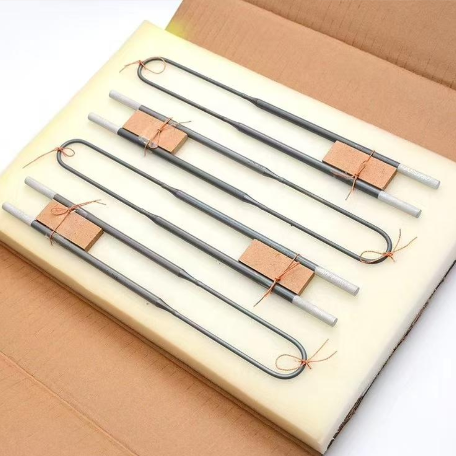
Molybdenum disilicide heating elements are often chosen for alloy and advanced material furnaces operating from around 1300°C to 1700°C. They offer excellent high-temperature oxidation resistance and stable operation in demanding cycles. For processes requiring faster recovery after door opening or heavy charging, MoSi2 may provide a more suitable thermal solution than an aging SiC setup.
That said, MoSi2 systems need careful mechanical support and suitable control design. If furnace geometry, support spacing, or electrical layout is poor, performance advantages may not be fully realized.
Support Components Also Matter
Protective pipes and graphite components are not secondary details. Silicon carbide protective tubes help shield thermocouples and other sensitive parts in aggressive furnace zones. Graphite products, when properly selected for atmosphere and temperature, can improve fixture stability and reduce distortion. Both influence measurement accuracy and thermal consistency.
Liao yang jia xin carbide co ltd has been focused on developing, manufacturing, and supplying SiC heating elements, MoSi2 heating elements, silicon carbide protective pipes, and graphite products since 2007, supported by more than 20 years of production experience. For alloy manufacturers exporting globally or running continuous high-temperature lines, consistent component quality is a practical factor in reducing temperature-related downtime.
What procurement teams should verify
Operating temperature range and atmosphere condition.
Required dimensions, tolerances, and installation layout.
Resistance matching and replacement grouping method.
Expected maintenance interval and spare-part planning.
Supplier experience with alloy furnace applications.
Common Mistakes That Keep the Problem Coming Back
Even after repairs, some plants still face repeated cases where the furnace cannot reach target temperature. This usually happens because the first intervention addressed the symptom but not the system condition behind it. In alloy processing, recurring temperature loss often has a maintenance or procurement pattern.
Replacing Single Elements in an Unbalanced Set
Installing one new SiC rod among several heavily aged rods may seem economical, but it often creates uneven current distribution. The new element may run differently from the old set, and the furnace still struggles to reach the required temperature. Group replacement or resistance-matched replacement is usually the safer approach.
Ignoring Furnace Loading Discipline
If the batch mass increases by 15% to 20% while the heating profile remains unchanged, the furnace may appear underpowered even though all components are functional. Overly dense stacking, oversized trays, and blocked airflow paths can all reduce effective heat transfer in alloy heat treatment and sintering.
Overlooking Measurement Drift
A plant may replace elements, wiring, and insulation, yet the actual issue remains an aged thermocouple. Sensor validation should be part of every major troubleshooting cycle, especially when the deviation develops gradually over 6 to 12 months.
Buying by Price Alone
Low-cost elements with inconsistent resistance, poor dimensional control, or unstable material quality can increase long-term cost through early replacement, extra energy use, and production interruptions. In B2B alloy operations, purchase value should be judged by total operating stability, not unit price alone.
Maintenance Planning to Prevent Future Temperature Loss
The most effective way to avoid emergency shutdown is to combine routine inspection with trend records. A monthly electrical check, quarterly insulation review, and scheduled sensor verification can reveal performance drift before the furnace loses 50°C or more. This is especially valuable in plants with continuous export production, tight delivery schedules, or alloy grades sensitive to thermal variation.
Recommended preventive routine
Weekly: record heating time to setpoint and observe any cycle extension.
Monthly: inspect terminals, current balance, and visible hot spots.
Quarterly: review element resistance trend and door sealing condition.
Every shutdown cycle: inspect protective pipes, supports, and fixture distortion.
At planned intervals: calibrate thermocouples and confirm controller parameters.
This routine does not require complex digital systems. Even a basic log covering 4 to 6 indicators can help maintenance teams detect whether the furnace is losing heating power, leaking heat, or drifting in control accuracy.
When a furnace cannot reach target temperature, the right response is not just to replace parts quickly, but to identify the exact loss point in the thermal system. For alloy applications, that means checking heating elements, electrical delivery, insulation condition, loading practice, and temperature measurement as one linked process.
With suitable SiC heating elements, MoSi2 heating elements, silicon carbide protective pipes, and graphite products, furnace operators can improve heating stability, reduce repeated shutdowns, and support more consistent alloy quality. If you need help evaluating worn elements, selecting replacement configurations, or improving high-temperature furnace reliability, contact Liao yang jia xin carbide co ltd to get a customized solution, discuss product details, and explore more high-temperature options for your alloy production line.
Tôi sẽ giới thiệu trang này cho đồng nghiệp app slot365 TONY06-29
in English
Cách giải thích rất dễ hiểu và logic hb88 ink TONY06-29
In English